From Zero to Custom Frame
Rather than building from a known frame, I wanted to engineer one from first principles - the way I'd approach any new mechanical system professionally. That means doing the analytical work upfront: pick components against target performance, simulate the flight characteristics, validate against a reference, then use those validated loads as structural design inputs.
Component Selection & Performance Targets
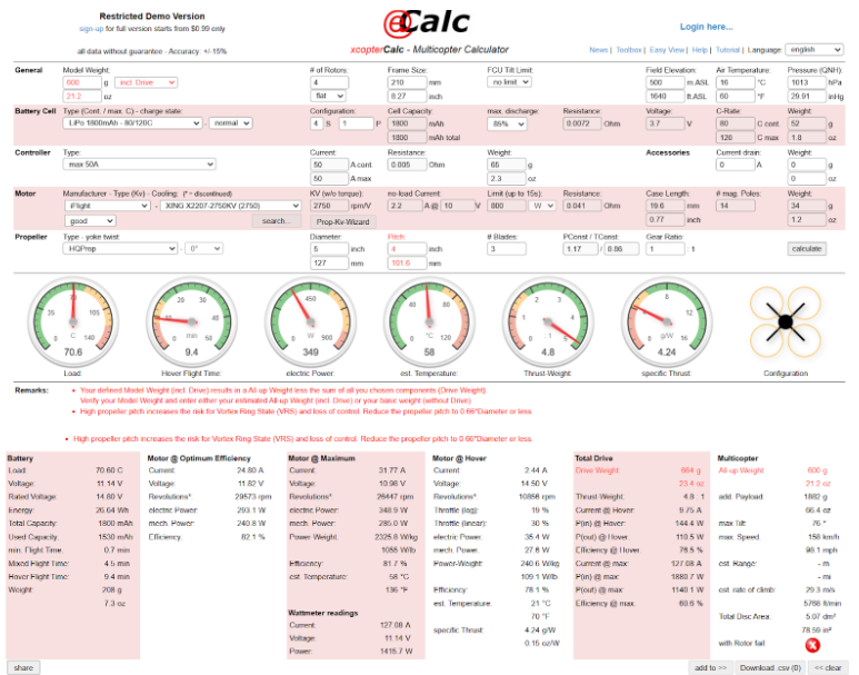
Defined the performance envelope first (thrust-to-weight, top speed, acceleration profile) and worked backward to size motors, propellers, and ESCs. Each component selection was justified against the target spec.
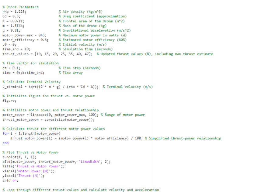
MATLAB Flight Simulation
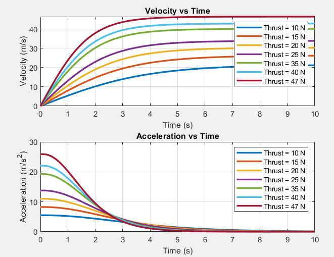
Wrote a custom MATLAB simulation using motor and prop characteristics as inputs, stepping through the dynamics to produce velocity-vs-time and acceleration-vs-time curves at varying thrust levels. Predicted maximum terminal velocity, peak acceleration, and theoretical impact force.
Validated by running the same inputs through an established external flight simulator widely used in the FPV community. Close agreement between my simulation and the reference gave confidence the loads were trustworthy enough for structural decisions.
Max terminal velocity, peak acceleration, impact force at terminal velocity, flight range - all key FEA inputs.
A simulation is only useful if its outputs are trustworthy. Cross-checking against a known reference catches modeling errors before they propagate into structural decisions.
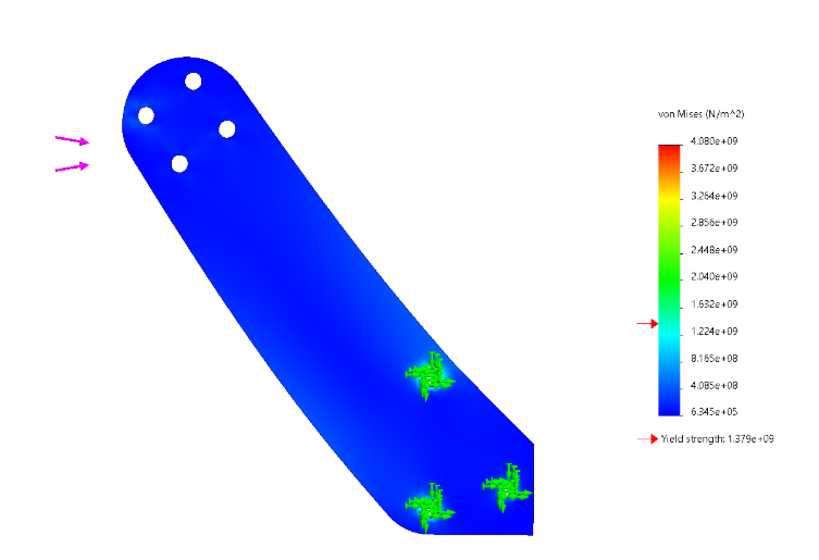
FEA - Sacrificial Arm Design
With validated impact forces, I ran finite element analysis on the frame with simulated flight loads as input parameters. The objective wasn't maximum strength - it was predictable failure.
The arms are designed as sacrificial structural elements: engineered to fail first and in a controlled manner on hard impact. This protects the center plate (FC, ESCs, camera) from damage. A snapped arm is a 5-minute swap; a destroyed FC stack is a hundreds-of-dollars rebuild. Sacrificial design is common in aerospace and automotive - crumple zones, shear pins, fuses - but rare in hobby FPV where most designers optimize for uniform strength.
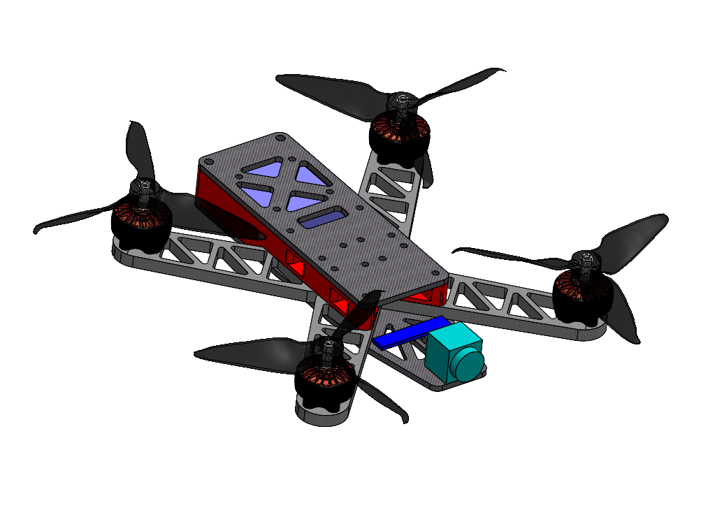
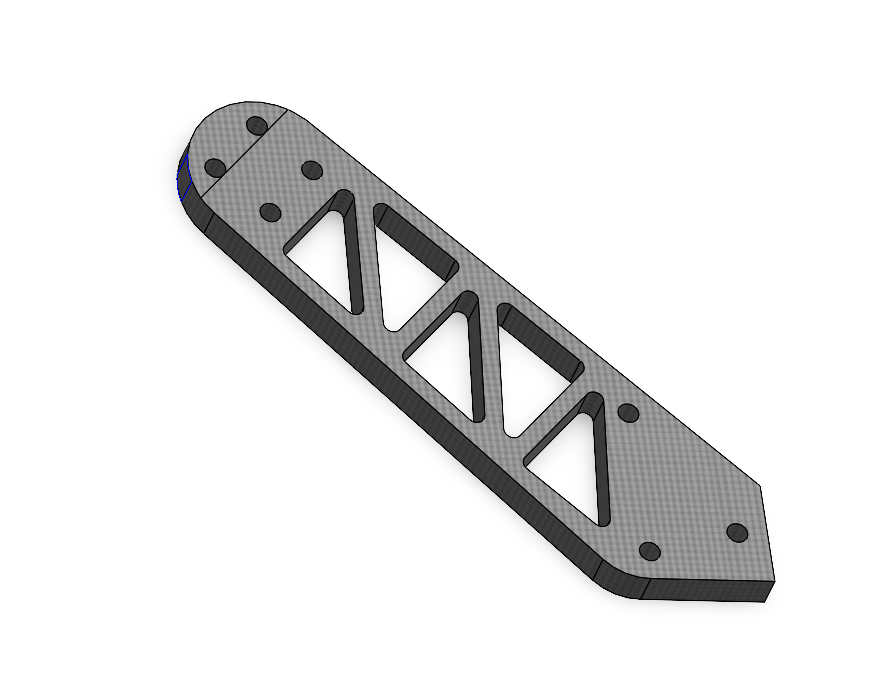
Compact 5-Inch Layout With Predictable Failure
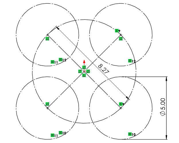
The frame is sized around 5-inch propellers, a useful middle ground between agility, thrust, and battery-carrying efficiency. I kept the frame as compact as possible so the center of gravity stays low and near the vehicle center.
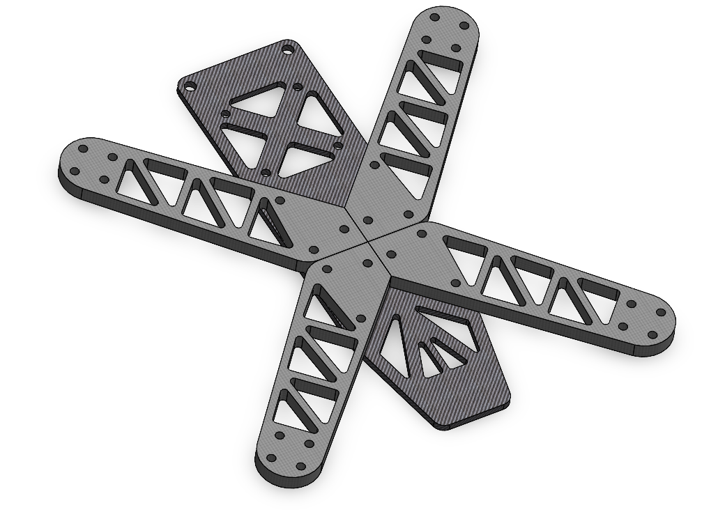
The arms brace against each other in an X pattern to increase rigidity while pockets remove material where it does not contribute much stiffness.
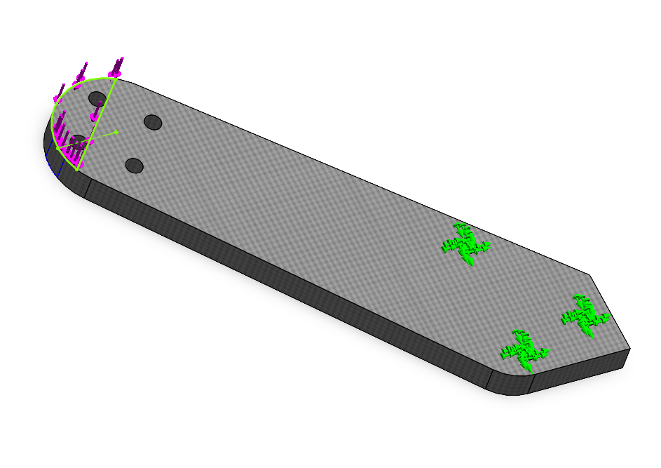
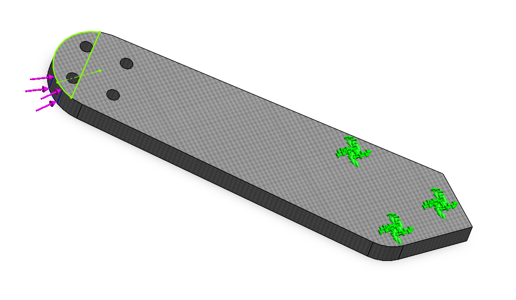
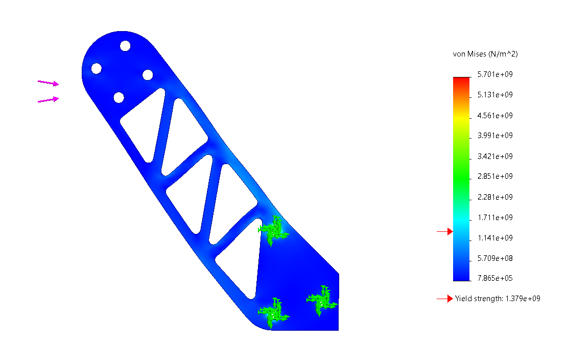
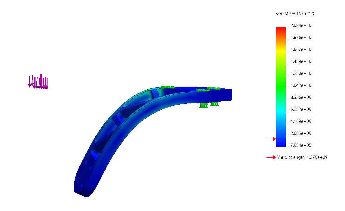
The first arm geometry was loaded in side and bending cases based on the flight simulation outputs. These studies exposed high-stress regions around the arm transition and motor mount area.
Those results drove the next geometry pass, with material redistributed to raise stiffness while preserving a preferred failure location outside the central electronics bay.
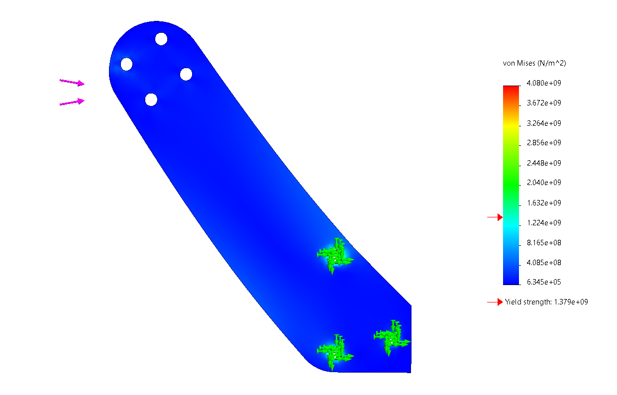
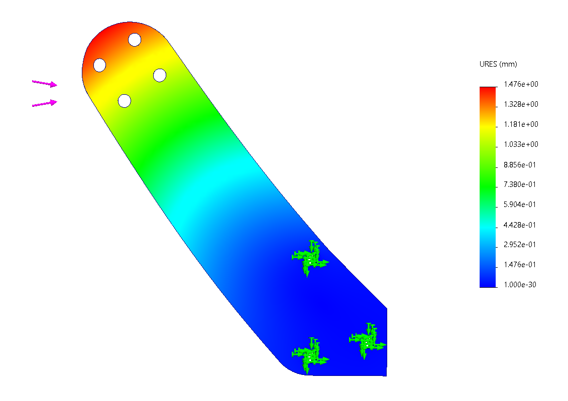
After several FEA passes, the final arm geometry reached the target strength while keeping the likely fracture point outside the central frame. The goal is not indestructibility; it is an inexpensive, replaceable arm protecting expensive electronics.
I also checked maximum acceleration loading. Deflection was negligible under that case, which supports stable flight and predictable control response.
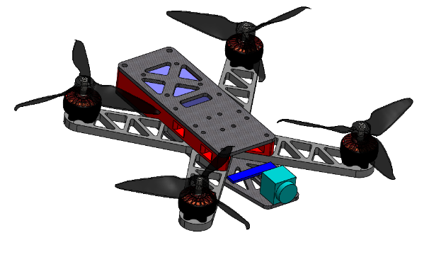
The final assembly model includes mocked electronics so the stack height, battery placement, prop clearance, and service access can be checked before fabrication.