More independent ownership across live manufacturing systems.
Returning for a second term, I continued development of the Rack Delatcher tool from my first co-op, owned a new station design from concept to production deployment, and led troubleshooting investigations across several active production lines. I also began mentoring incoming co-ops, assigning tasks and providing technical guidance alongside my own project work.
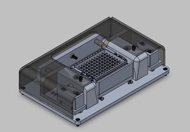
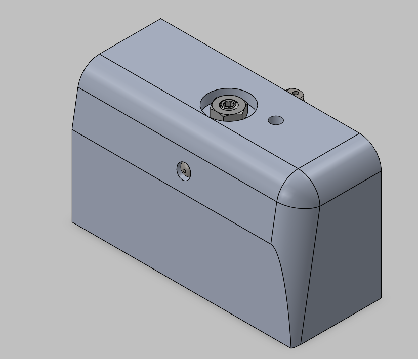
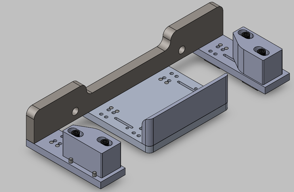
Rack Delatcher - Version 2
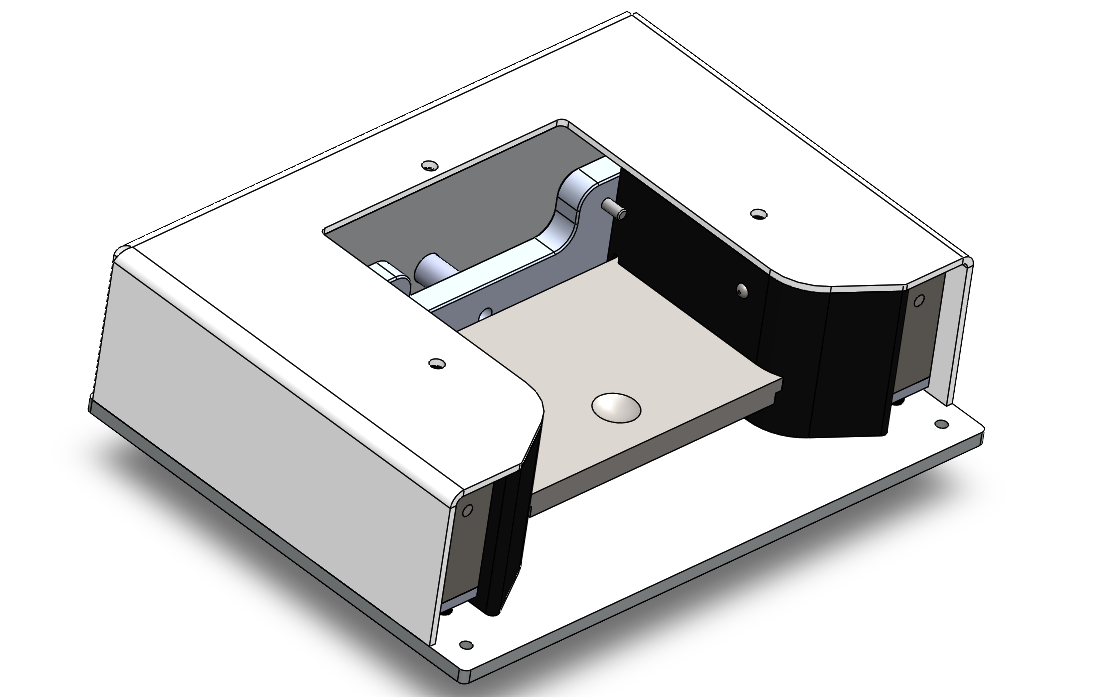
Subassembly breakdown
The v2 development began with a formal breakdown of the tool into four subassemblies, establishing a cleaner design language and making future maintenance and iteration easier to reason about.
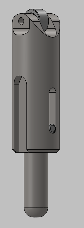
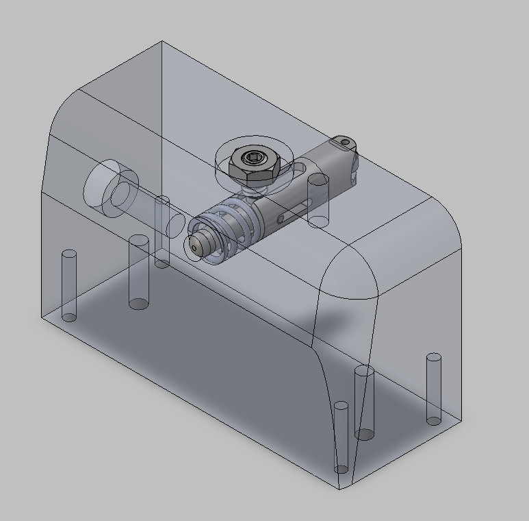
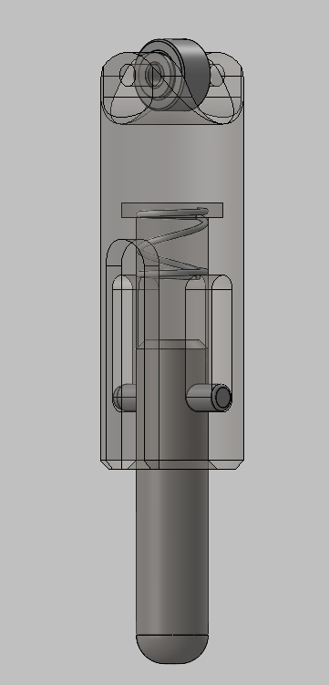
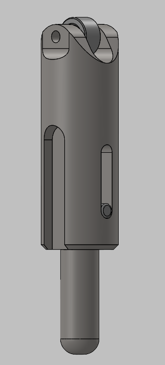
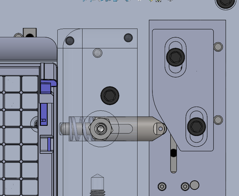
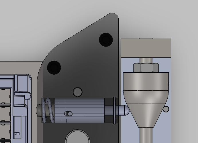
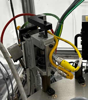
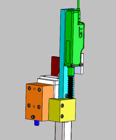
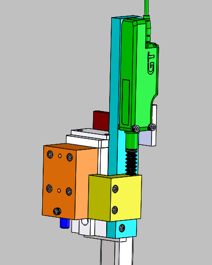
Cam follower redesign
Production use exposed significant wear on the main cam action. The original sliding-contact cam follower was replaced with a roller bearing, reducing friction and increasing input force multiplication
Original sliding contact
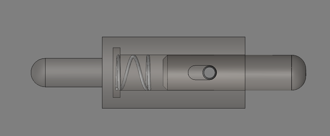
V2 roller bearing
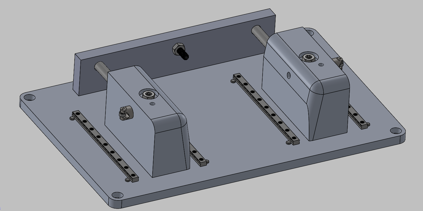
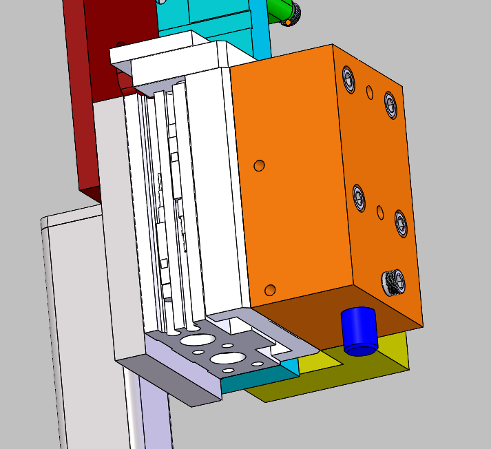
Manufacturability and robustness improvements
With the roller bearing addressing wear, additional structural and tolerance improvements prepared the design for more reliable fabrication and production use.
- Thin components were reinforced to reduce flex and breakage risk.
- A draft angle was added at the part entry to improve engagement margin.
- Two additional linear rails were added for lateral stability.
- Geometry was simplified to reduce overall cost.
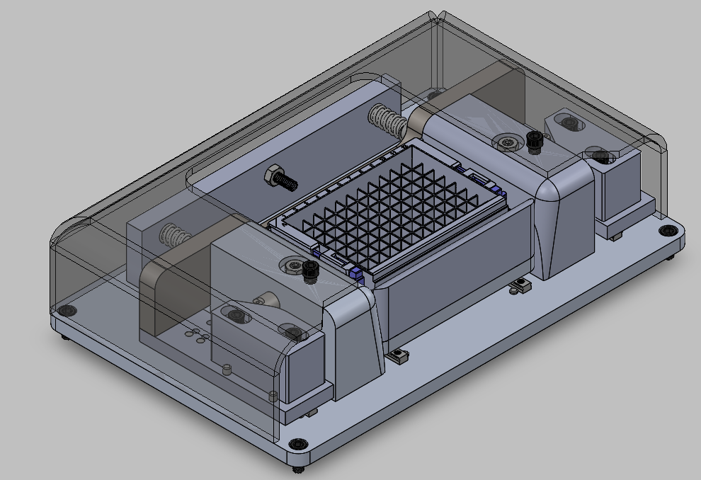
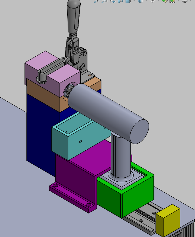
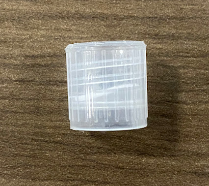
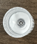
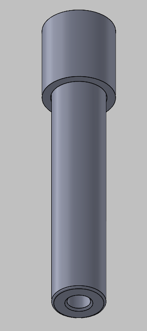
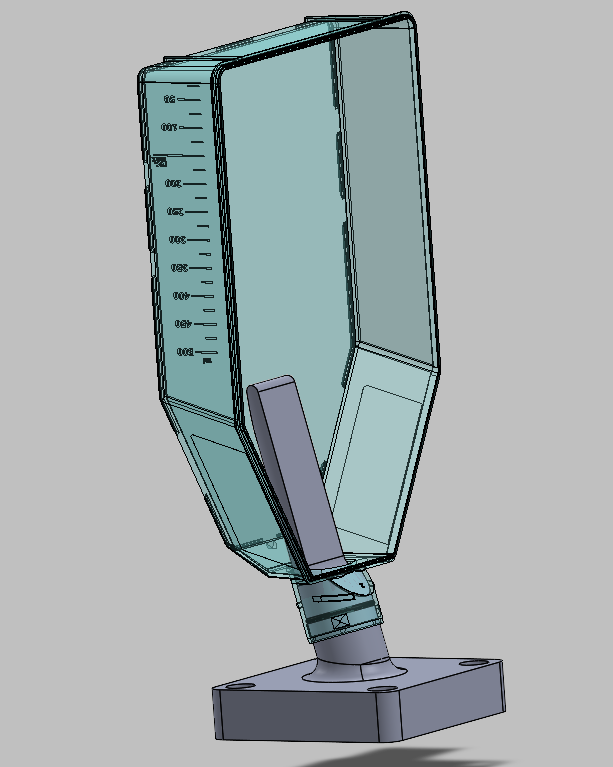
Tube Cutting Station
Problem
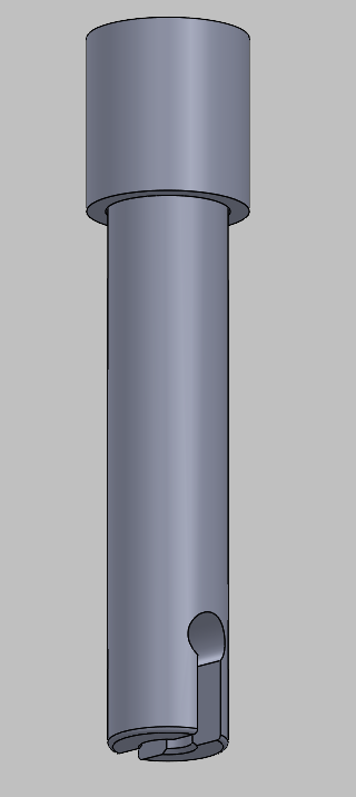
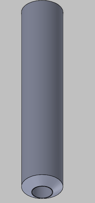
Stems for the dispensing jug product line were previously sourced externally. To reduce supply chain risk and gain internal control over the process, ThermoFisher needed a safe, repeatable in-house cutting process from scratch.
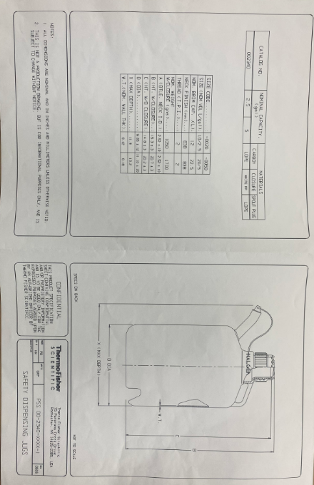
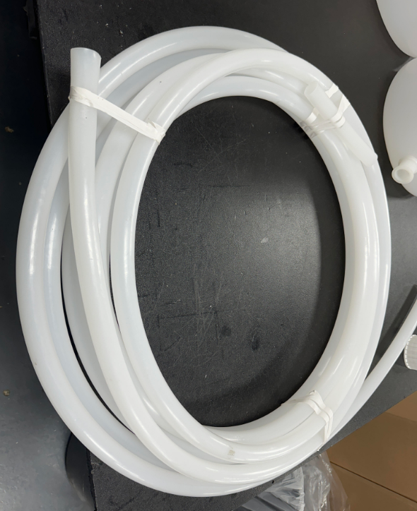
The goal was a self-contained station that could repeatably cut tubes to length and ream out the spout end without requiring specialized operator skill.
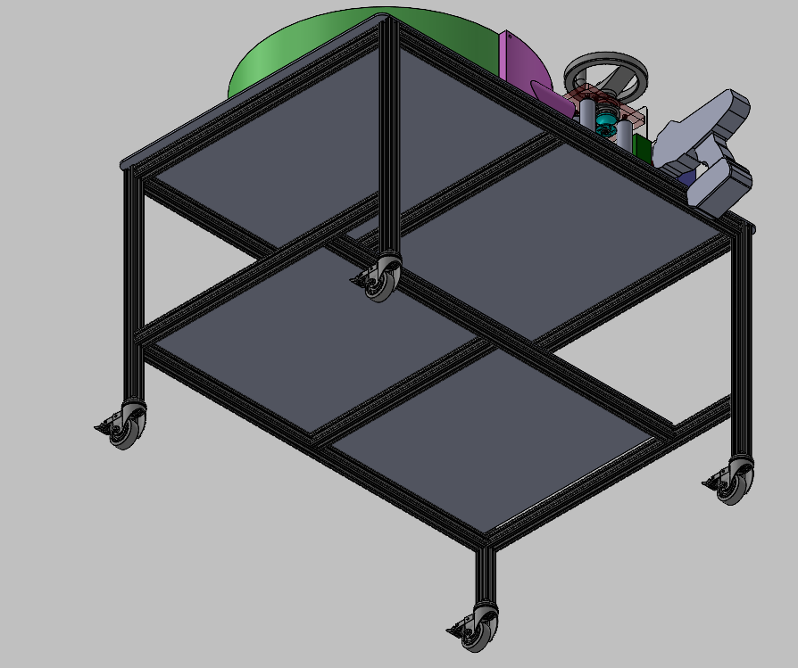
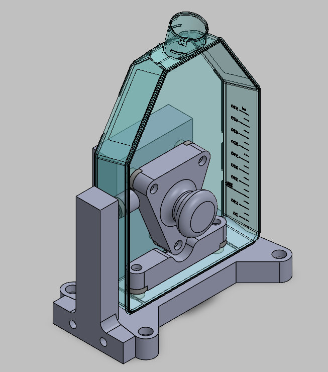
Concept
The station was designed around a custom ergonomic table with powered cutting and reaming tools mounted on the bench, part and battery storage in the frame, caster wheels for mobility, and a layout that minimized reach and awkward motion.
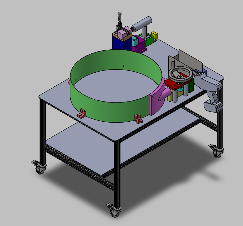
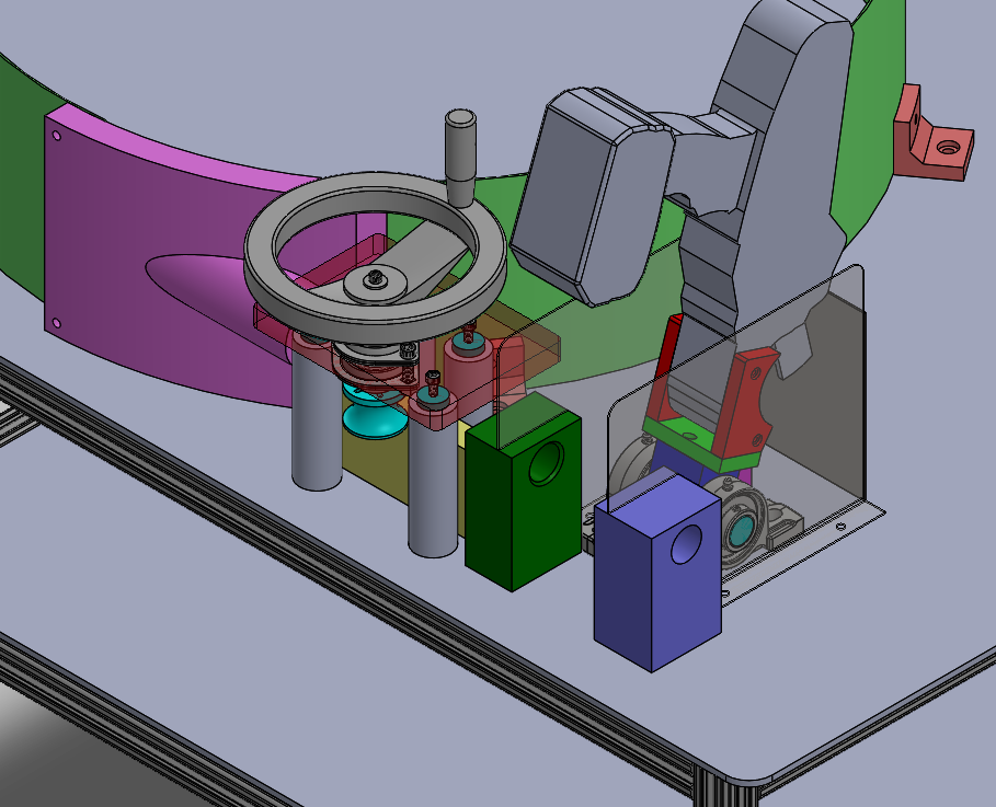
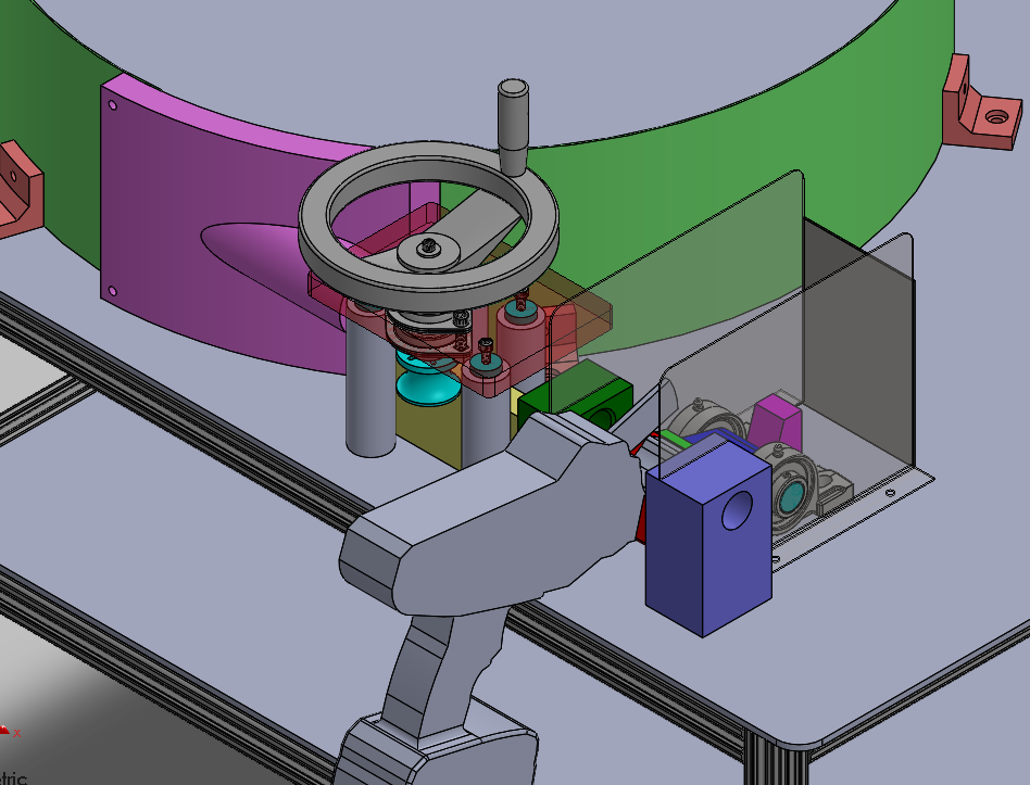
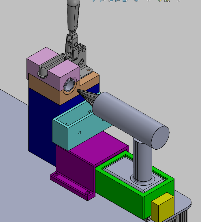
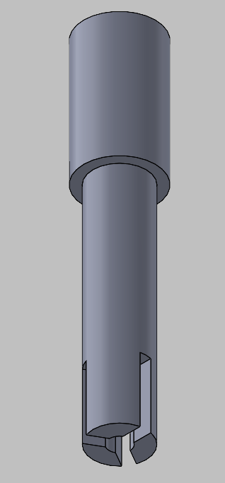
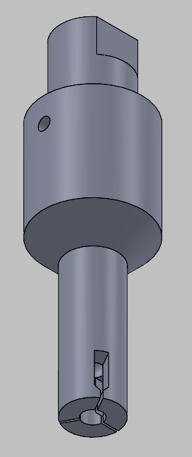
Cutting and reaming process
The final process is a four-step operation: swing the cutter into the work area, feed the tube to length and cut, load the cut tube into the staging area and clamp down, then activate the drill and push in to ream out the stem. Unfortunately, my co-op ended before I could see my design implemented in production.
Closure Gasket 1 - Troubleshooting and Redesign
An aging closure gasket assembly machine was generating chronic failures and quality escapes. Instead of patching individual symptoms, I led a systematic diagnosis of failure modes and drove a multi-station redesign targeting the root causes.
- Gasket cutting and seating were the primary contributors to failures.
- The inspection system was difficult to adjust and did not emulate part function.
- Nest height repeatability was inconsistent across stations.
- A secondary seating step was needed to reduce inspection failure rate.
Highlight 1 - gasket seating tool iterations
I designed a series of tamping tools, V1 through V5, each incrementally improving gasket seating. The iteration process exposed the actual root cause: concentricity and sharpness of the upstream cutter were the real contributors, not the tamping geometry itself.
This was a strong example of using iterative experimentation to identify a root cause rather than treating symptoms.
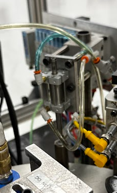
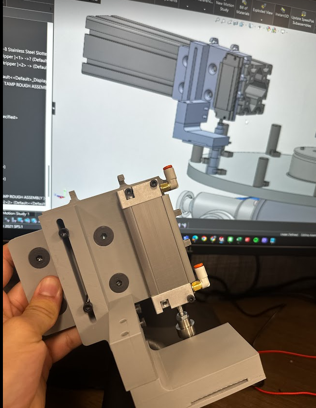
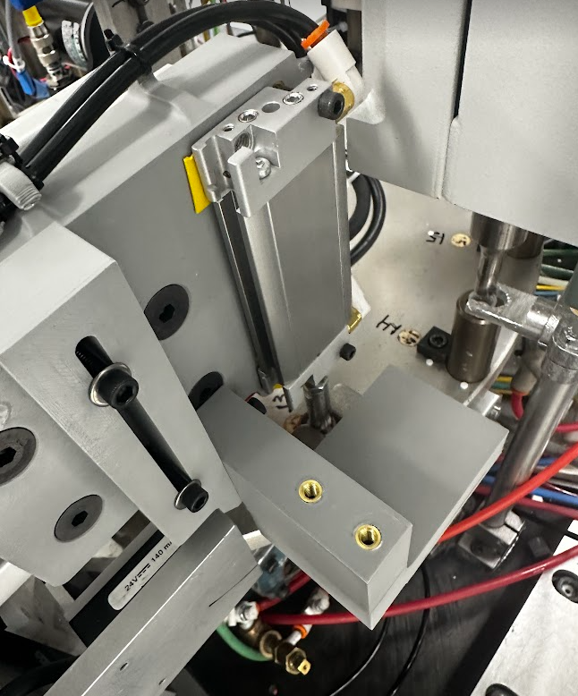
Highlight 2 - secondary tamp
Post-weld, gasket material was getting caught on the closure threads, causing aesthetic failures at final inspection. I designed and implemented a secondary tamp station after the weld and before final inspection, with three-axis adjustability and stainless steel contact surfaces to prototype. The machine was over 30 years old so there were no CAD files to work with. This was a quick, effective way to solve the problem.
Highlight 3 - controls discovery
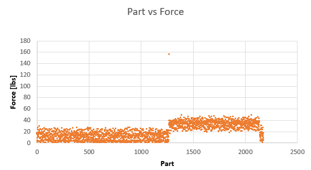
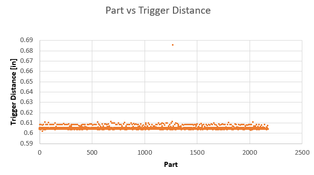
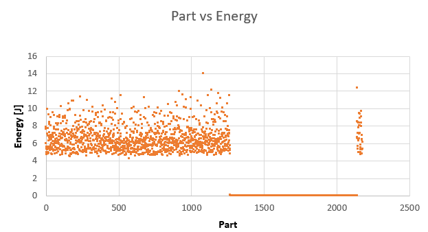
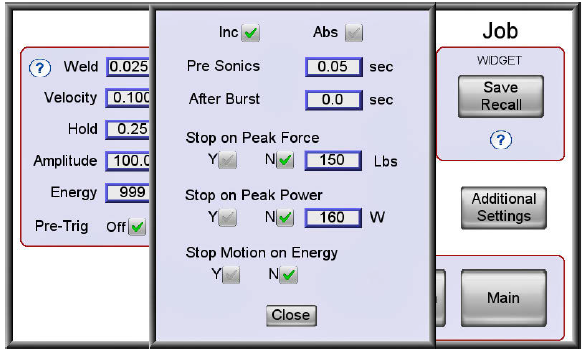
During machine runs, a critical controls failure mode was uncovered: the weld horn over-traveled and made direct contact with the part nest. Force feedback spiked past the set limits, the weld horn shut off, but the machine continued running and produced unwelded parts before the issue was caught.
The root cause was traced to feedback limit configuration in a secondary settings menu. The fix required enabling lower-bound limits, adjusting the magnitude, and verifying the welder's PLC output logic.
Full redesign breakdown
Station 3 and 6 - orientation and gasket check
An LVDT replaced the harder-to-adjust previous system. Shaft collars on a sliding rod determined gasket position through proximity switches.
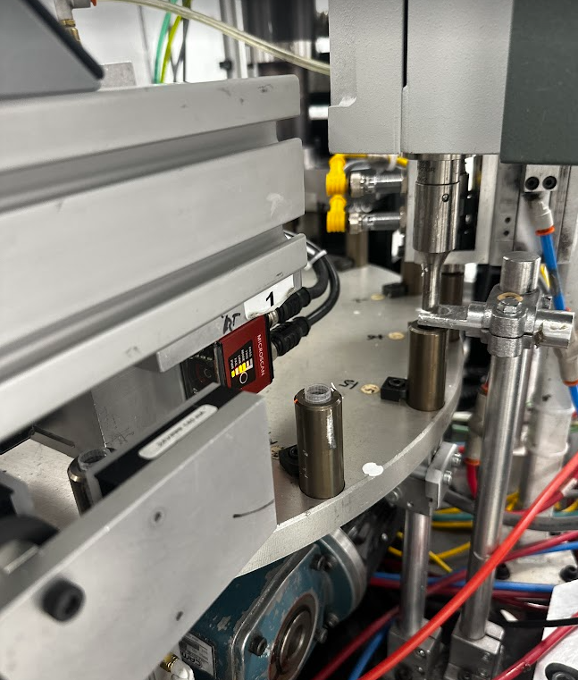
Nests and station 16
Redesigned nests supported the underside of the closure for improved weld performance. Sliding Kiss blocks presented nests to a consistent height across stations, improving station-to-station repeatability.
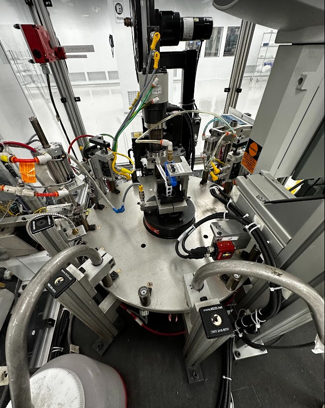
Apex - Capping Line Troubleshooting
Two related quality issues were causing stoppages on the Apex capping line: particulate contamination on vials and thread stringing on closures. Both degraded product quality and required frequent operator intervention.
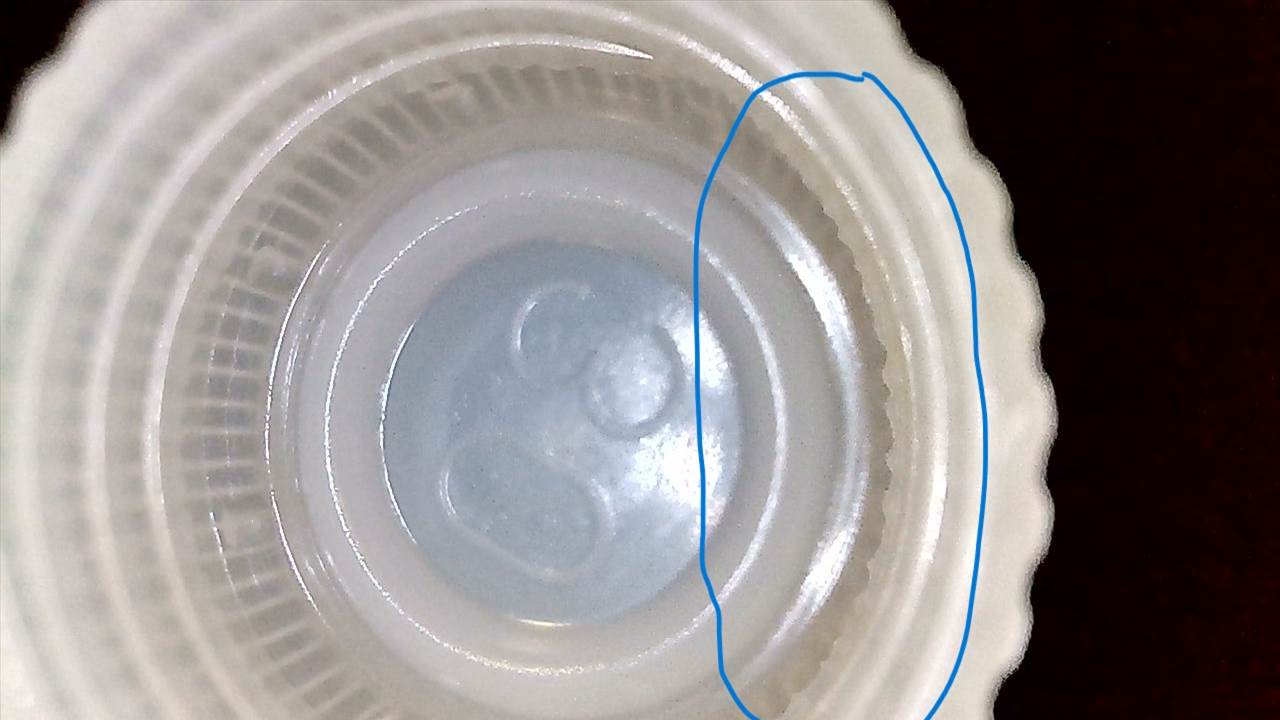
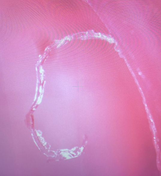
Stringing - DoE and parameter optimization
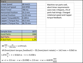
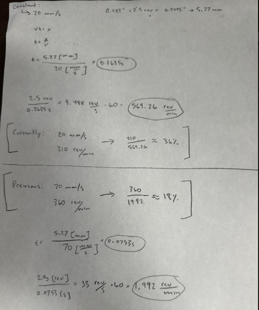
I conducted a Design of Experiments varying capping sequence parameters to isolate what was driving stringing. The investigation showed the LINMOT capping actuator was operating at the wrong linear and rotational rates, so its motion did not match the pitch of the closure thread geometry.
I calculated the correct rotational and linear speed required to match the closure pitch. Hardware limits prevented a perfect match, but the updated parameters moved the process closer to the ideal pitch rate and substantially reduced stringing and reduced capping failures by 18%.
Particulate mitigation
To address particulate under tight time constraints, I quickly designed and 3D printed a custom air knife to direct airflow down into the reject chute, pulling particulate away from the product path. Particulate levels dropped after machine cleaning combined with optimized LINMOT settings. The air knife did not produce the expected additional reduction, a useful negative result for the next troubleshooting path.
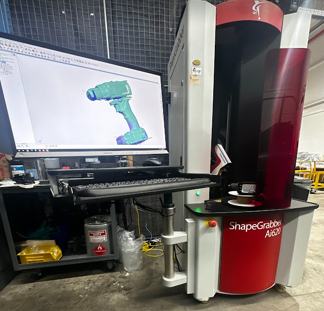
ShapeGrabber - In-Process Optical Inspection
Defective molded parts, including flash, runout, and dimensional variation, were entering automation lines without being caught upstream. The goal was to develop an in-process inspection method using a ShapeGrabber laser scanning system to catch defects before they reached production. The laser was capable of measuring features as small 0.00025". That's about as small as red blood cell!
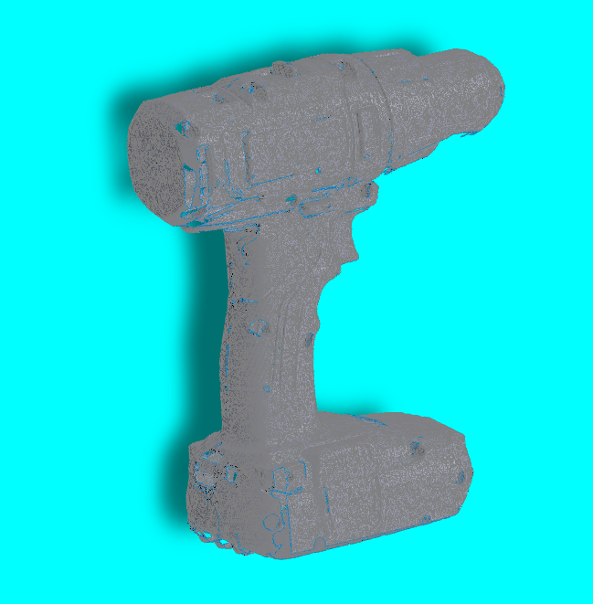
I completed 12+ hours of machine training with an OGP applications engineer, then ran experiments to characterize scanner capabilities by scanning a drill bit and stitching together a point cloud as a baseline test.
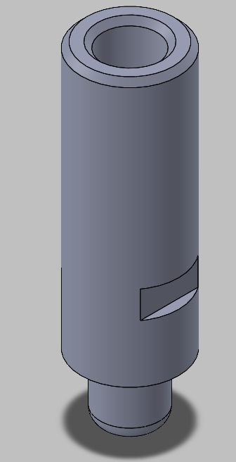
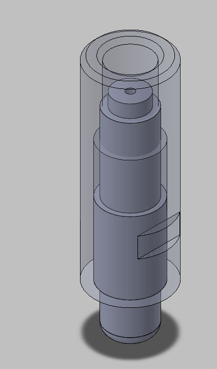
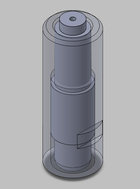
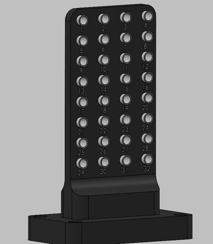
Concept 1 - two-stage vial fixture
The first fixture concept addressed both internal and external vial features using two dedicated stages: a mandrel fixture for external features and a counterbore fixture for internal features, with scans stitched into one inspection result.
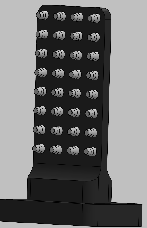
Concept 2 - vertical fixture
The fixture was redesigned to scan parts vertically, which produced promising results but introduced a new problem: getting a uniform coating of scanning spray while minimizing part handling that could introduce inconsistency.
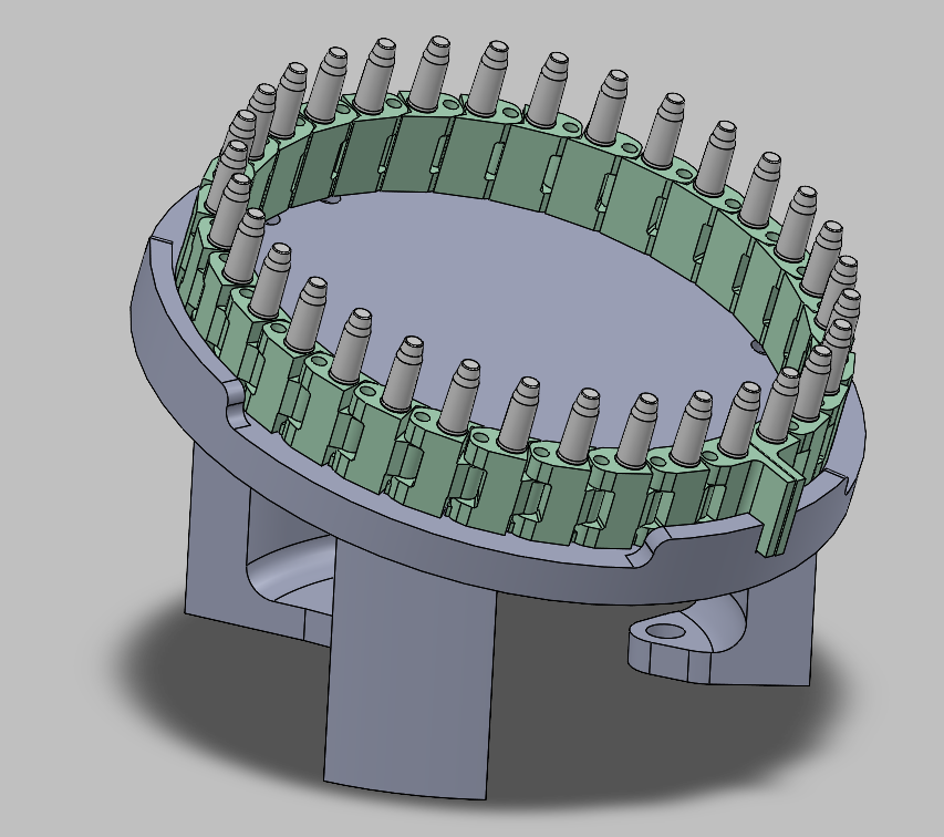
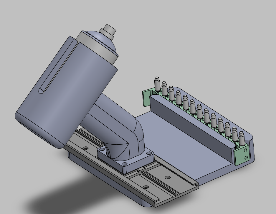
Concept 3 - chain link spray station
To solve the spray uniformity problem, I designed a chain link mechanism that transports parts in a straight line through the spray station without requiring handling. The chain contains interchangeable mandrels for different vial heights, then links mount on a circular stage sized to fit within the laser's field of view.
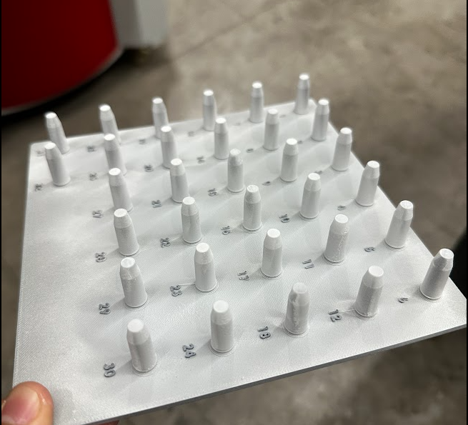
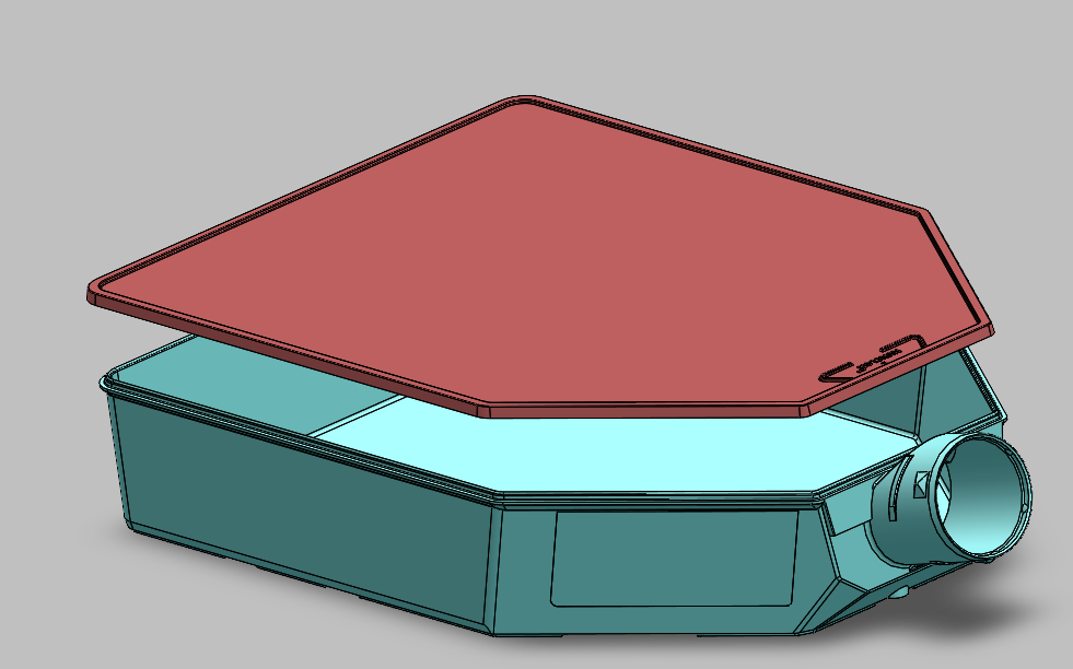
T225 Flasks - Burst Test Failure Investigation
T225 culture flasks were failing burst tests during quality control, triggering an investigation into the manufacturing process. The suspected root cause was misalignment between the energy director centerlines on the flask body and the lid groove centerlines, a dimensional relationship critical to ultrasonic weld strength.
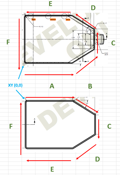
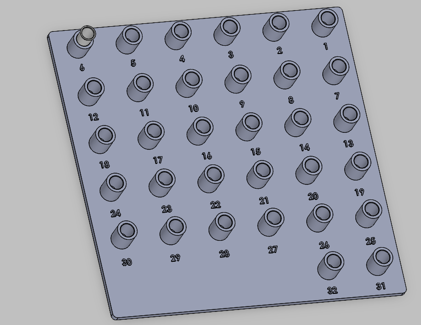
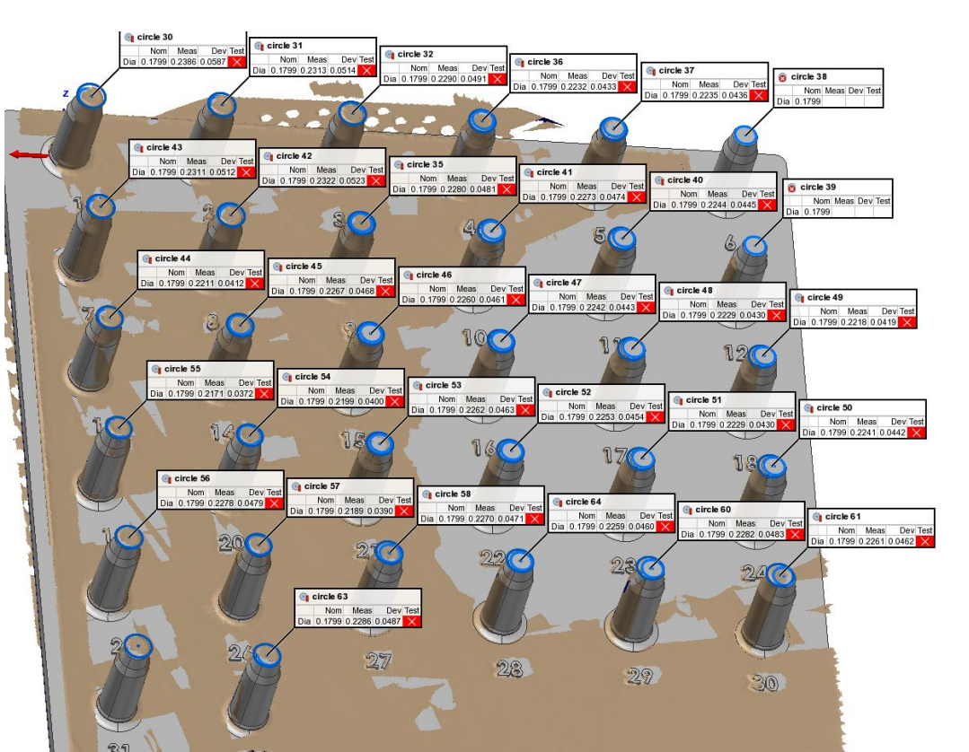
CMM inspection development
Working with Quality Engineering, I developed a CMM inspection program to measure centerline positions and characterize fitment. The program struggled to achieve acceptable Gage R&R in a Type 2 MSA study; repeatability degraded across repeated measurements on the same part, indicating an issue with the alignment method rather than the fixture alone.
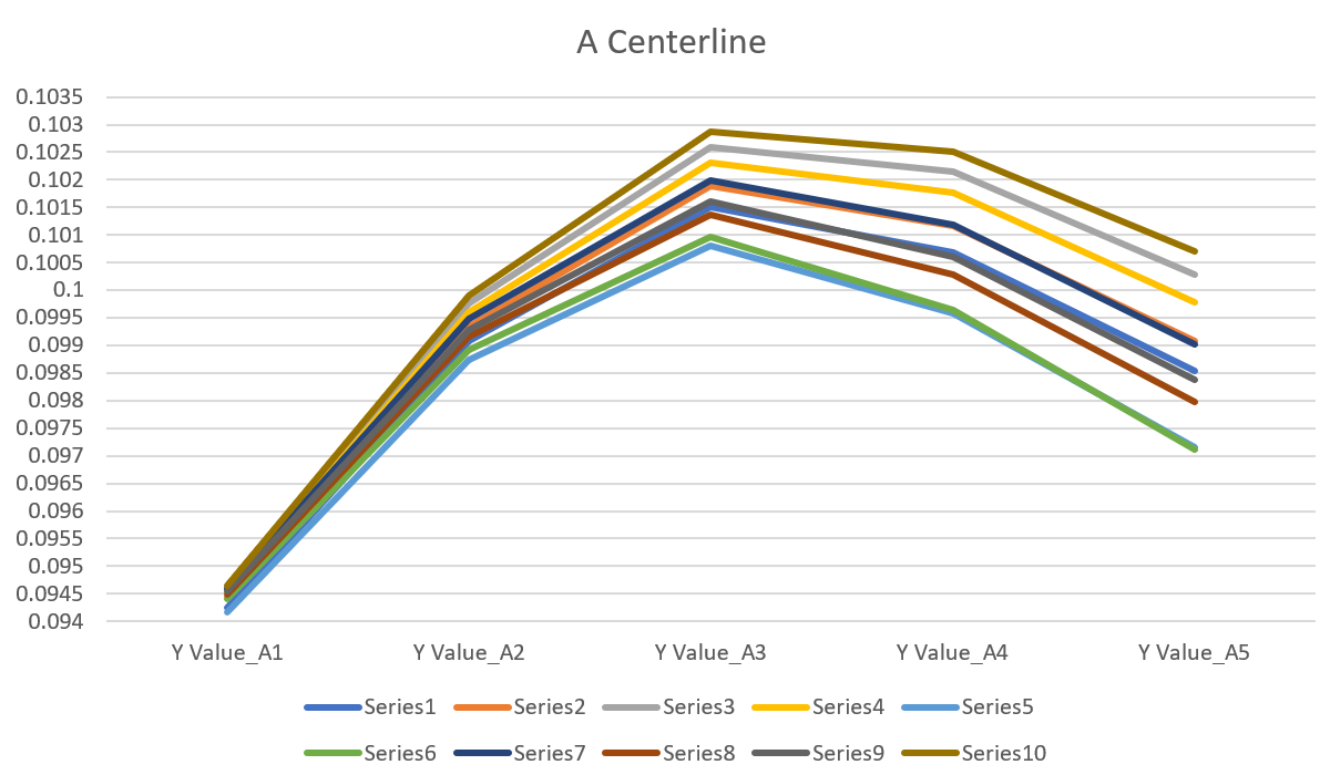
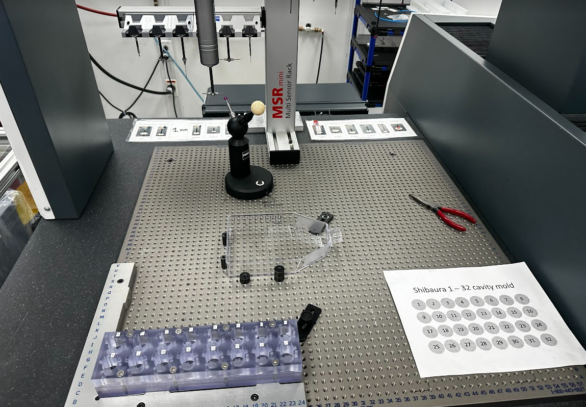
I developed multiple vertical staging fixtures to establish the datum from the part's feet, a more stable reference than the internal cavity. After analysis, the team switched to smart scope measurements with user-defined centerline input, which provided more stable and repeatable results.
Line 4 - Production Line Optimization
Layout optimization
Line 4 was relocated on the production floor to reduce travel distance between stations for operators. The condensed layout improved ergonomics and reduced non-value-added motion, a direct Lean manufacturing application.
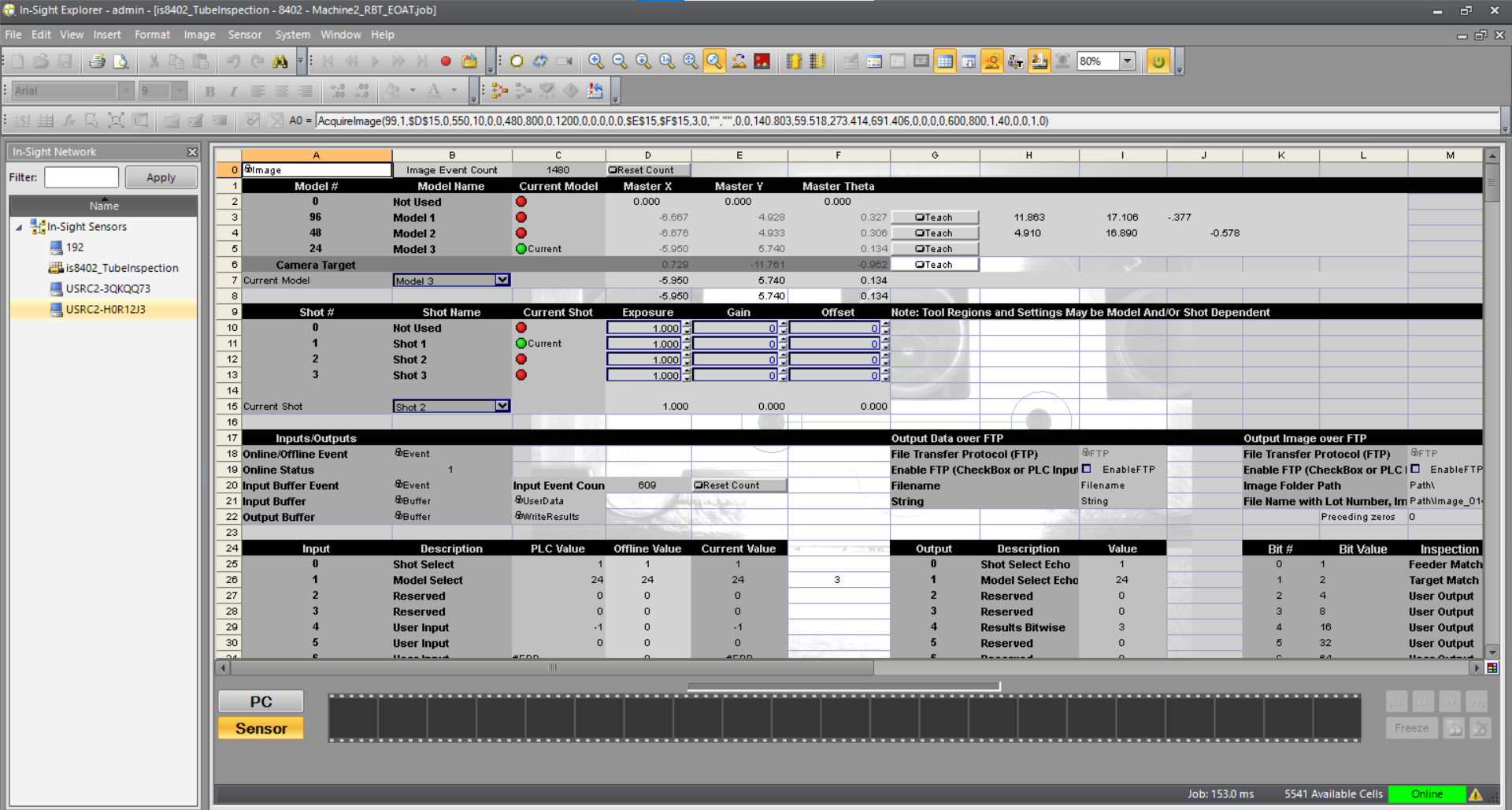
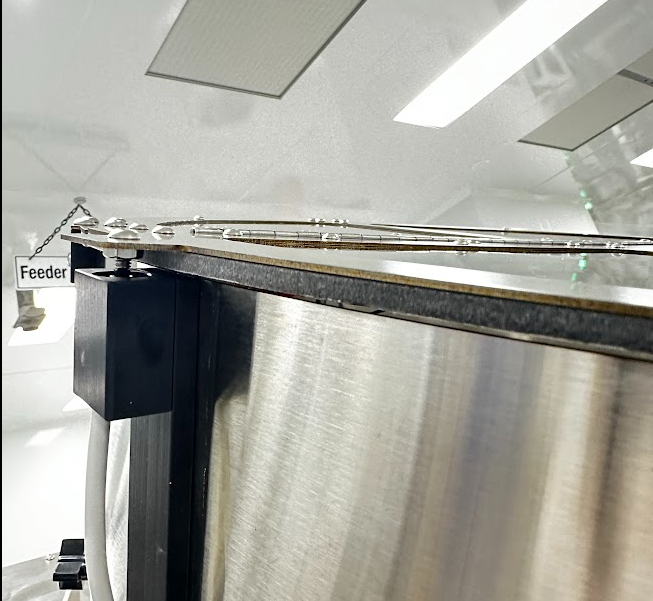
Reteaching the vision system
Moving the line shifted tubeloader bowl positions outside the thresholds of the previous vision system. I retaught the vision reference points and LVDT measurement positions to match the new physical layout.
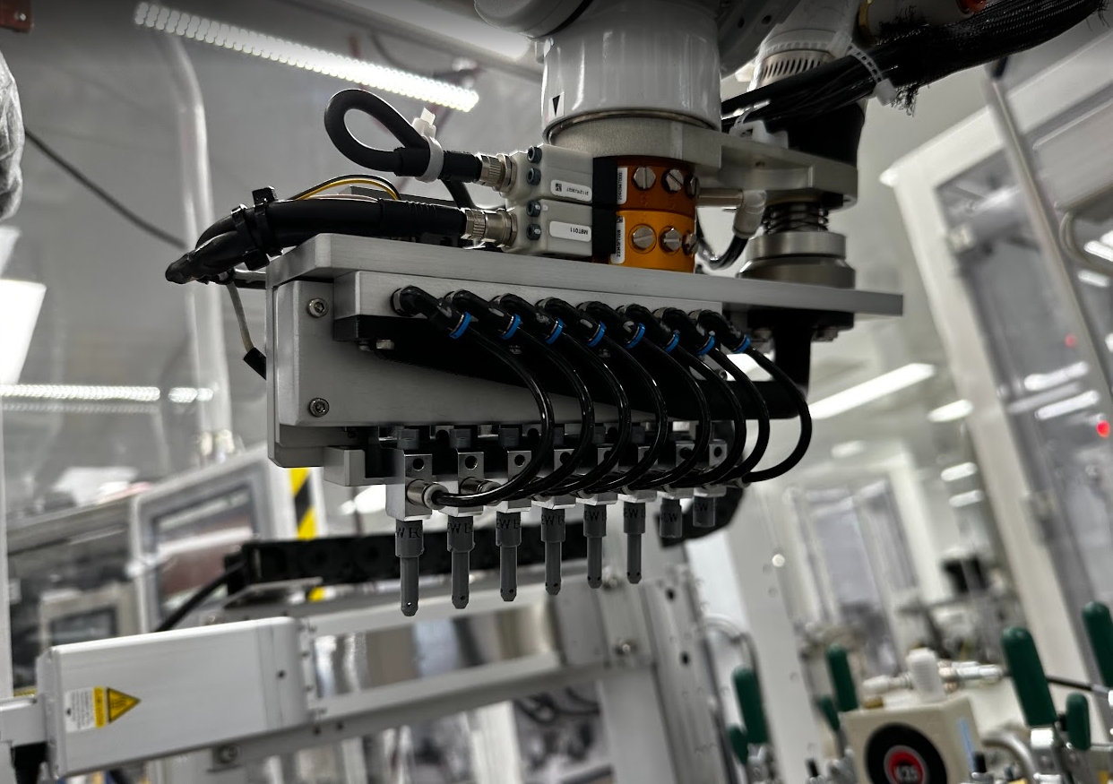
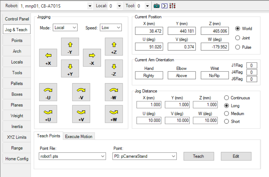
Reteaching the tubeloader arm
The robot's local coordinate system had shifted when vision offsets were updated, requiring all pick positions to be retaught. I retaught positions for all three bowl configurations, 96-well, 48-well, and 24-well, and updated the guide documentation. The vacuum actuated fingers were also modified to improve suction and release. Concentricity was critical.
Other Projects
Alongside primary project work, I contributed to a range of floor-level engineering tasks and tooling designs as production needs arose.
Kinex Capper - safety and sensor work
Two targeted Kinex capping machine improvements: a cover designed to eliminate an identified pinch point hazard and a new proximity sensor mount for the lid.
More floor projects and tooling
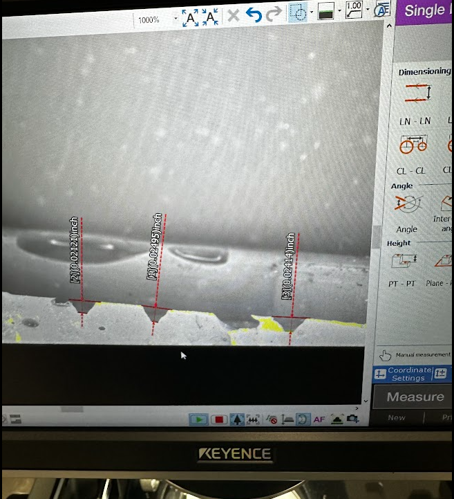
Stamping Tool Measurement
Letter-height measurement support for production staff.
Measurement Detail
Additional inspection and measurement context.
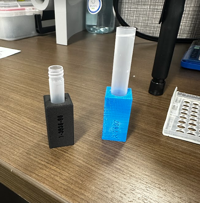
Vial Holder
Quality assurance vial holder for floor checks.
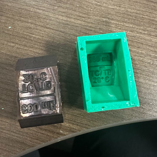
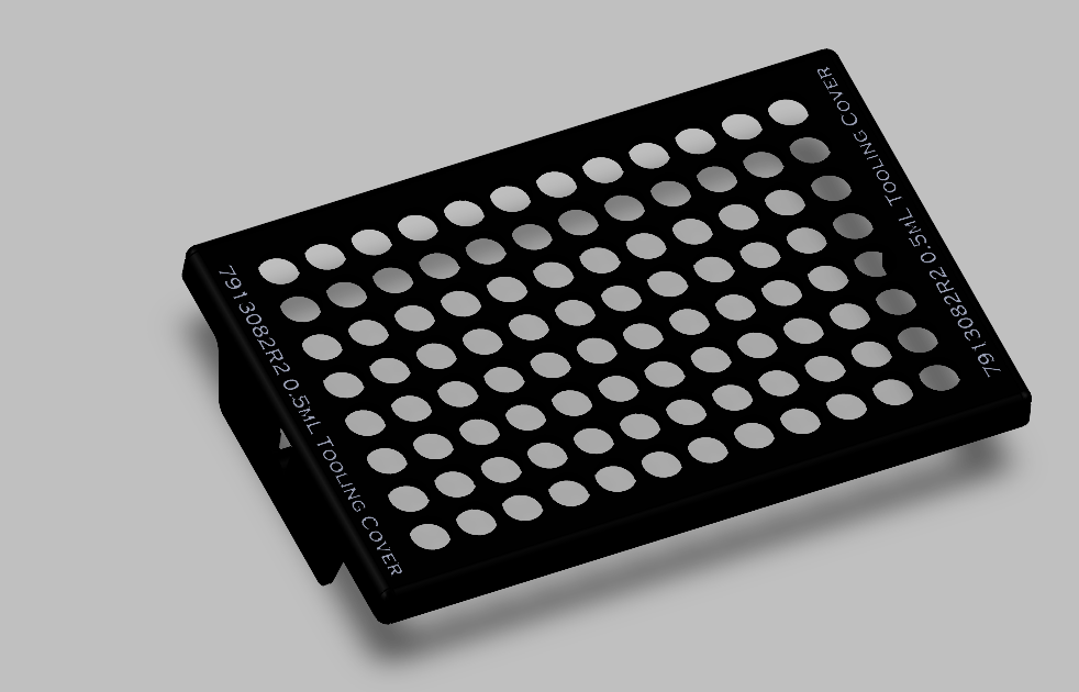
Hot Stamp Rack Lid
Rack lid with embossed letters for hot stamping work.
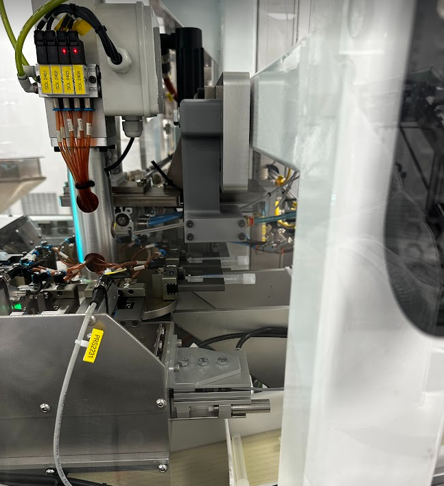
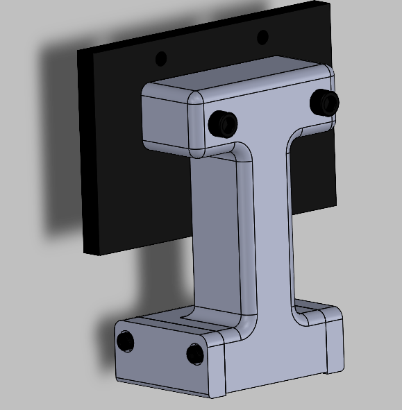
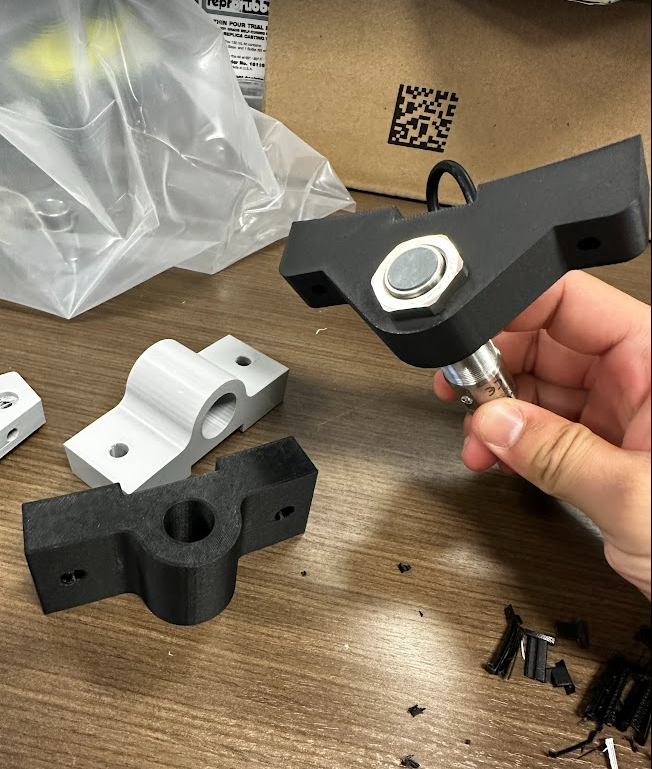
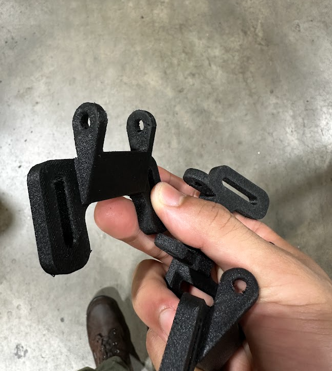
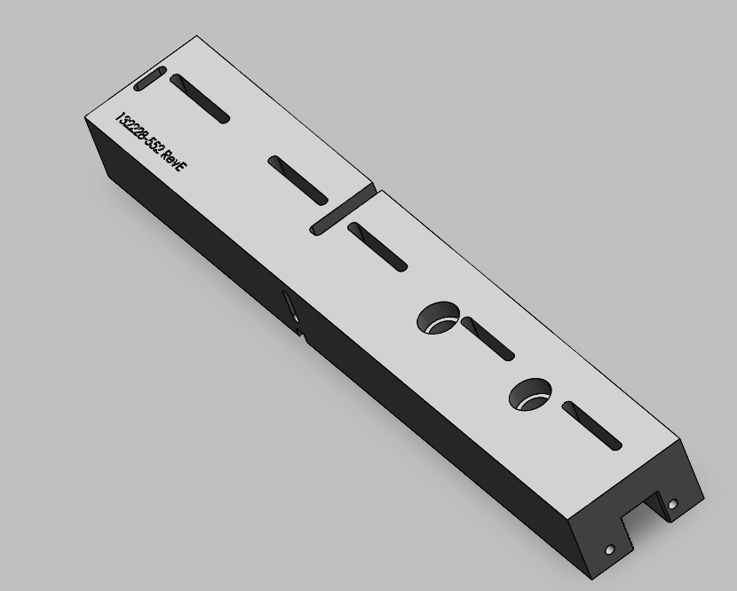
CG1 Door Bracket
Small bracket design supporting machine maintenance.
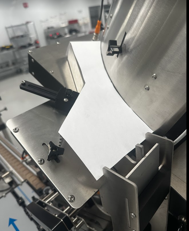
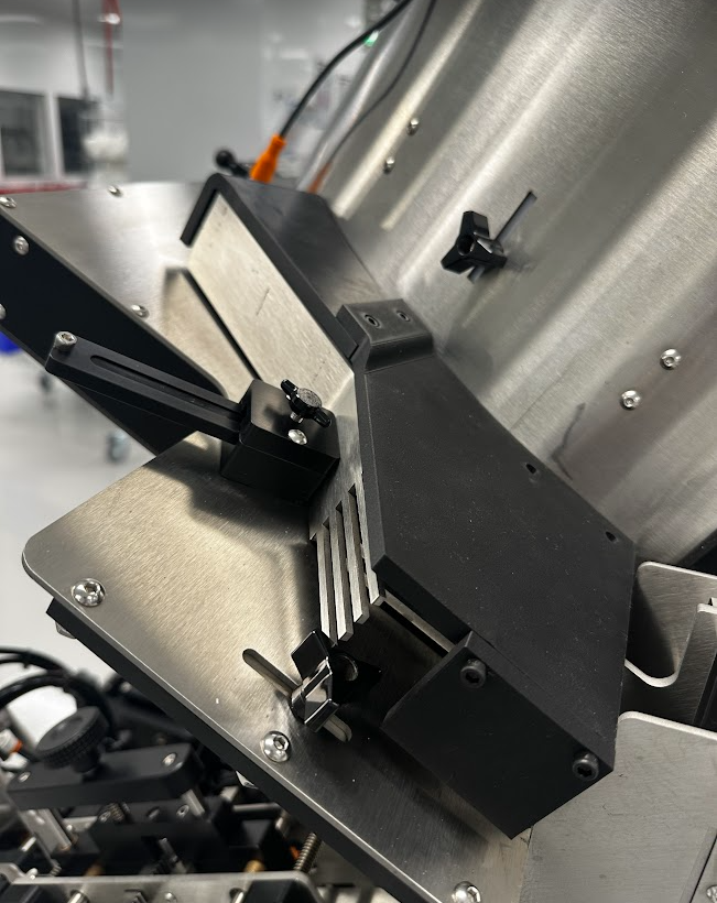
Apex Part Tunnel
Inline part tunnel design for the Apex process.
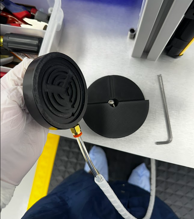
Mr. Big Puck Holder
Production support holder for Mr. Big tooling.
What I Learned
Troubleshooting and Root Cause
- Risk mitigation
- Defining constraints and intent
- Systematic failure mode isolation
SolidWorks and Drawings
- Part and assembly modeling
- Engineering drawings and GD&T
- Datum structures and PDM practices
Manufacturing Processes
- Additive and subtractive manufacturing
- Pneumatic and powered tooling
- Ultrasonic welding
Lean and Six Sigma Methods
- Design of Experiments
- Gage R&R / MSA
- Ergonomic and cycle time analysis
Quality and Metrology
- CMM programming
- Laser point cloud scanning
- Inspection method validation
Controls and Automation
- PLC logic review
- Robot pick-position programming
- Machine vision setup
Delegation and Mentoring
- Mentoring incoming co-ops
- Task assignment and prioritization
- Technical guidance and review